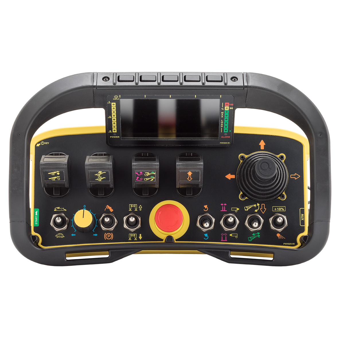
WC-R+
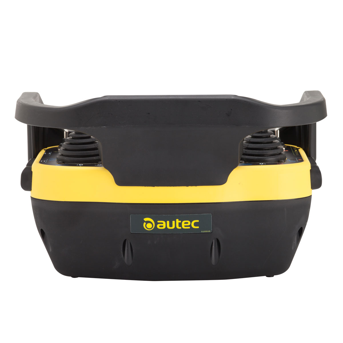
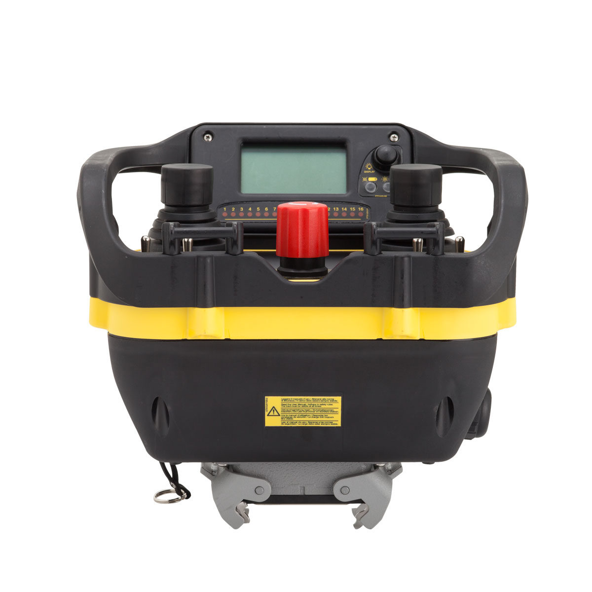
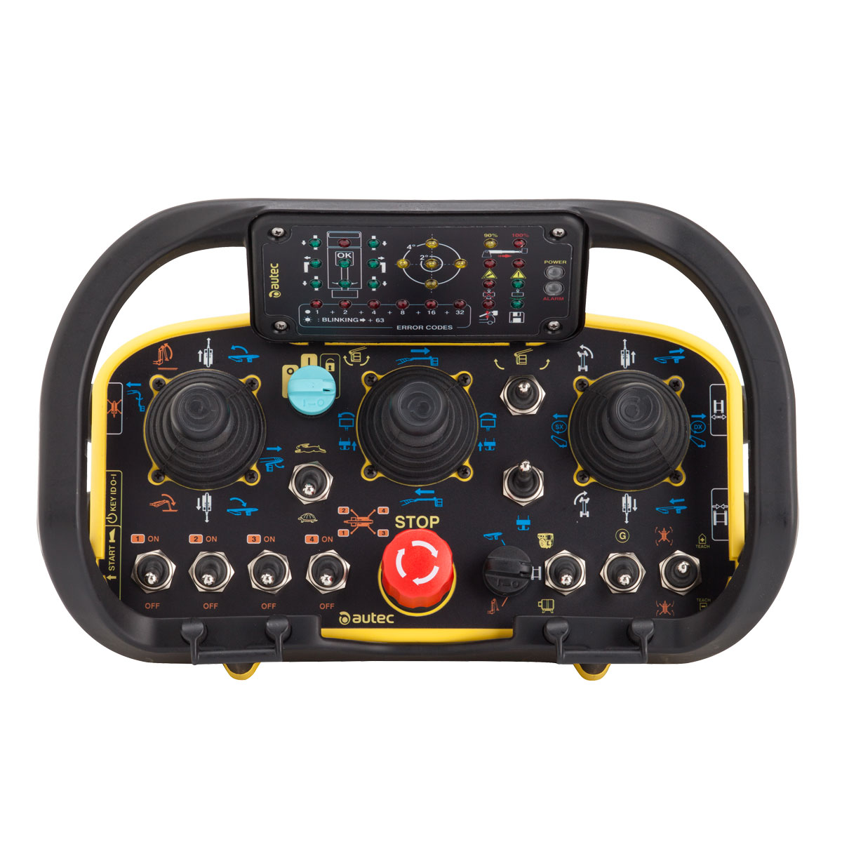
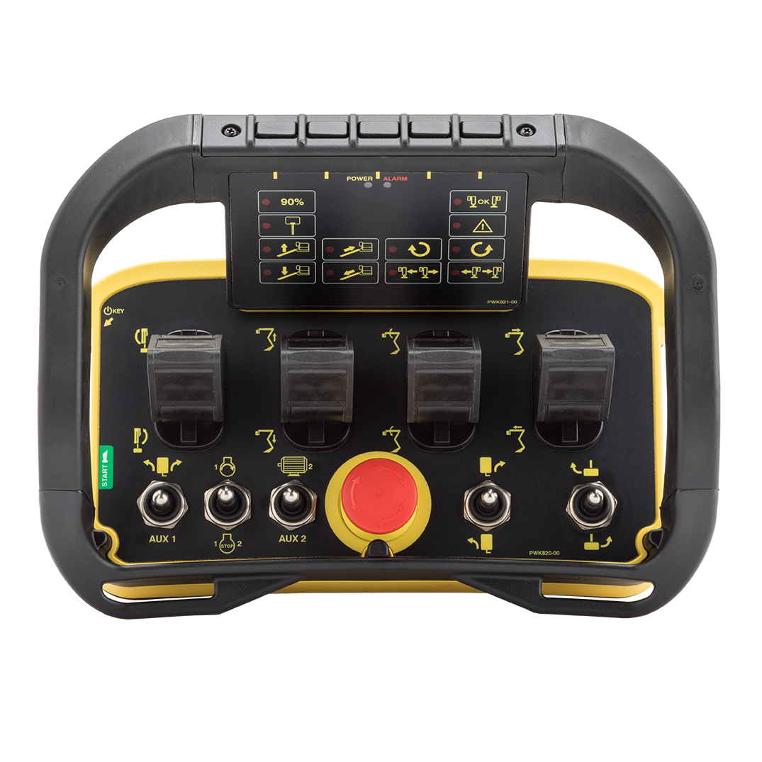
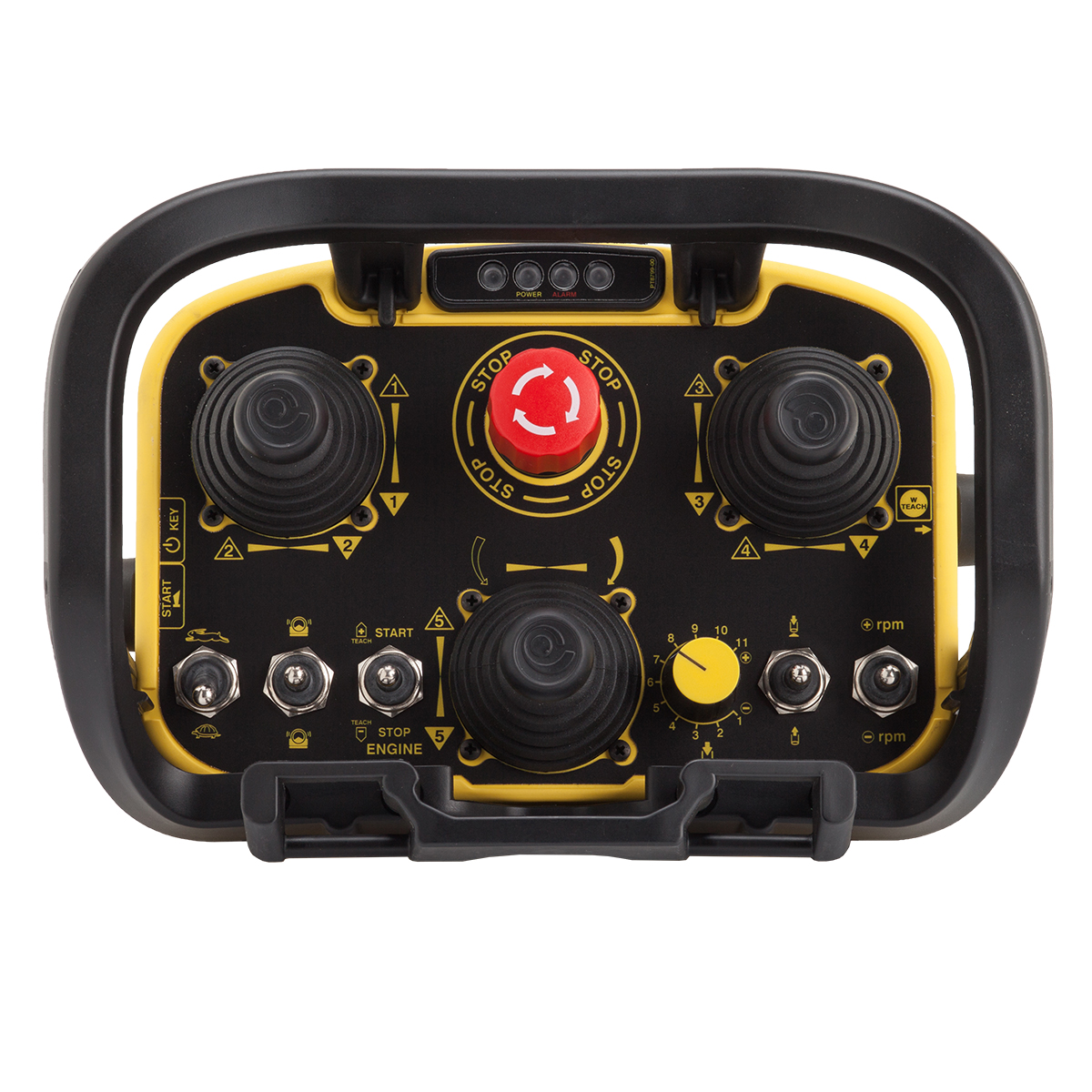
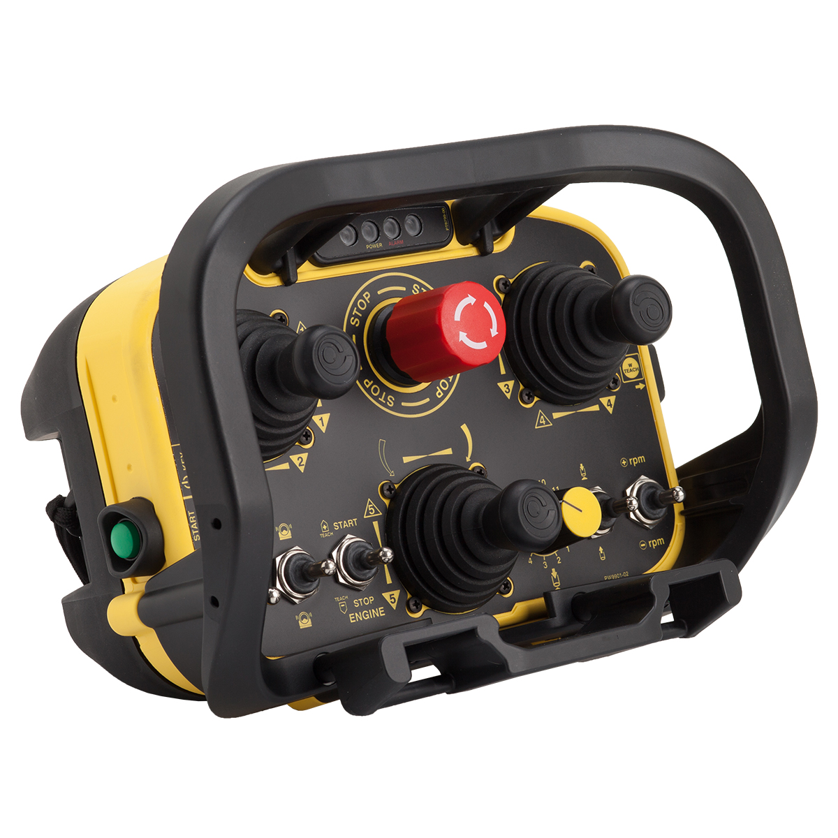
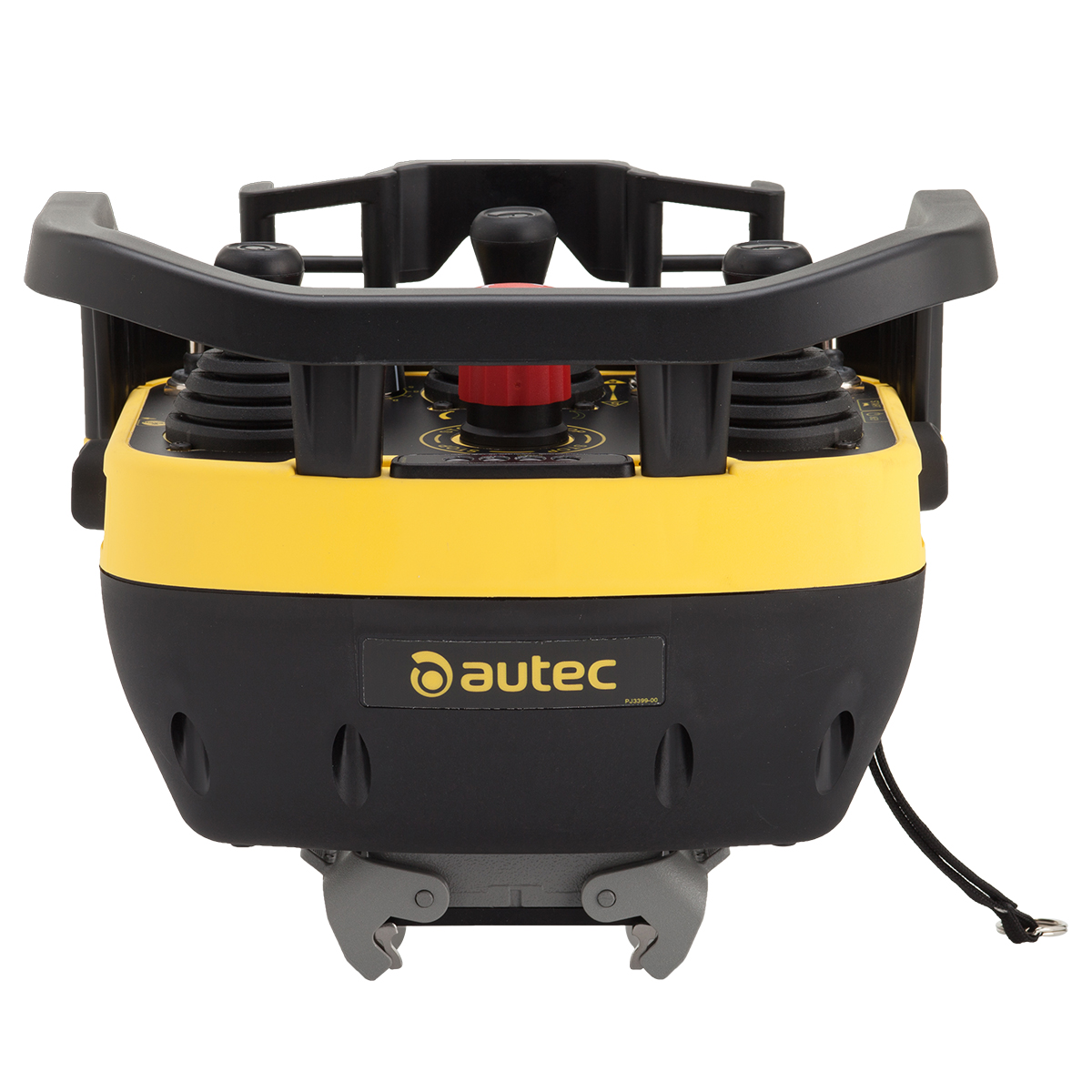
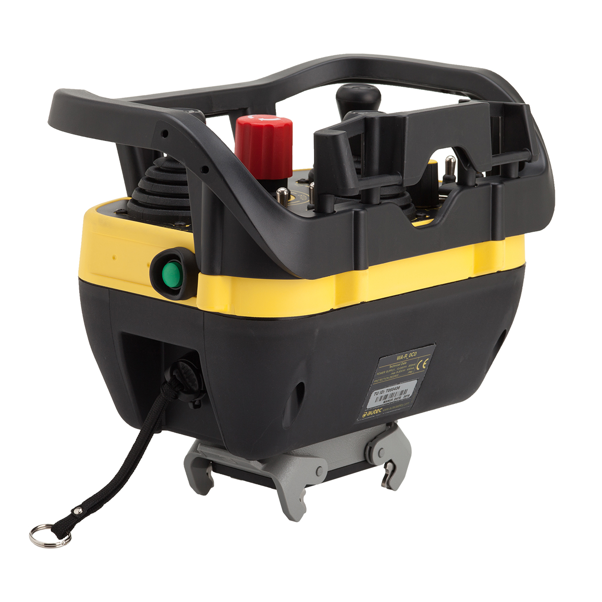
Cable controlCable control regular size including 4 digital outputs, a fieldbus output (CANopen), 4 digital inputs and a removable power keyswitch.
Accessories
Shoulder harness
Waist belt
STOP or EMERGENCY STOP
This cable command has a red pushbutton that can be used as either STOP or EMERGENCY STOP. This is possible thanks to the electrical characteristics of the pushbutton and provided that it is properly wired to the machine. STOP is defined as a function that allows to stop the machine and/or take it to safe conditions. EMERGENCY STOP, as defined in Machinery Directive, is a function that enables to avoid an actual or impending danger. The pushbutton used in the cable control can perform either a STOP or EMERGENCY STOP function because it conforms to all the applicable international standards as ISO EN 13850, IEC EC 60947-5-1 and IEC EC 60947-5-5. The use of this button as either STOP or EMERGENCY STOP depends on the machine. More specifically, it depends on its risk assessment, its characteristics, its application and the work area in which it operates.


Options
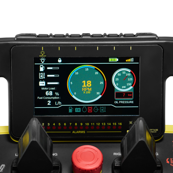
4.3" TFT LCD display (480x270 pixels, 65536 colors)
The display features extreme brightness and readability even in particularly sunny conditions. It is programmable via CODESYS or Jmobile. It has 16 signaling LEDs and five or six buttons (depending on the model) for interaction. In addition, an optional encoder is available to facilitate navigation.
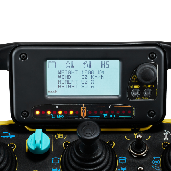
2.7" transflective LCD graphic display (128x64 pixels)
The monochrome display is ideal for displaying customizable signals and icons. It is equipped with 16 LEDs and has one button for interaction.
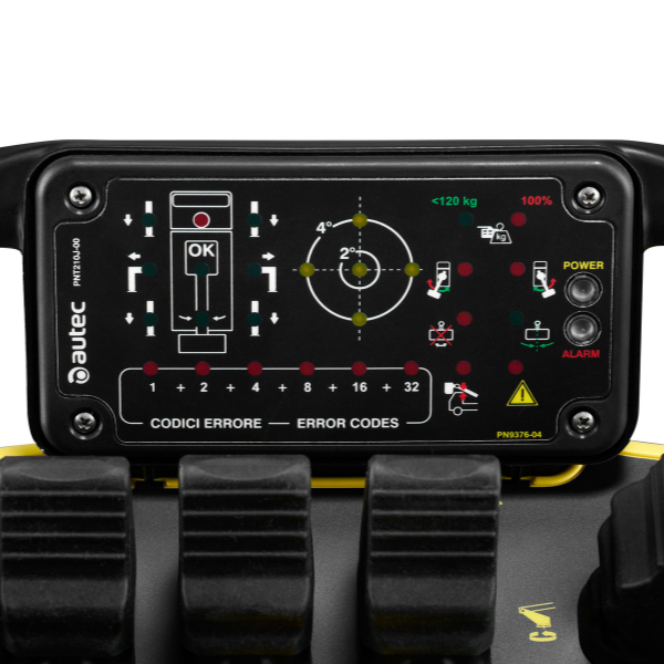
32 LED Matrix
32 diagnostic LEDs are available. The light intensity can be customized, and a NIGHT & DAY mode is also available.
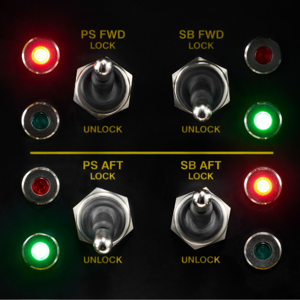
LED on panel
Possibility to insert LEDs on the panel to provide feedback regarding specific maneuvers/selections on the machine.
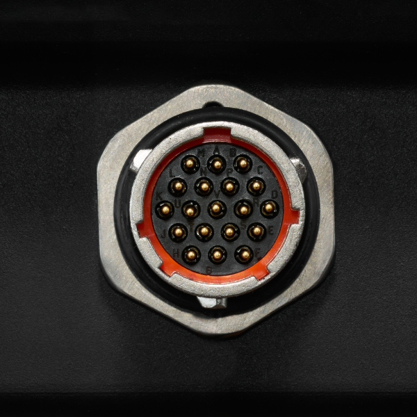
Souriau circular connector 10 or 19 pins
Souriau circular connector with 10 or 19 pins.
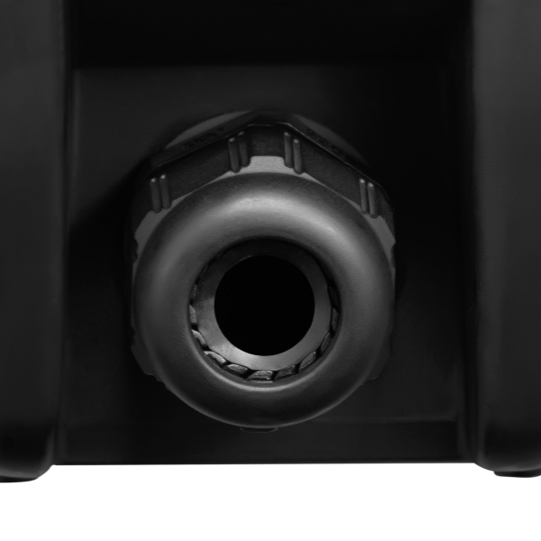
Output on cable gland and multipole cable
Passthrough connector used for installing the output on cable gland and multipole cable.
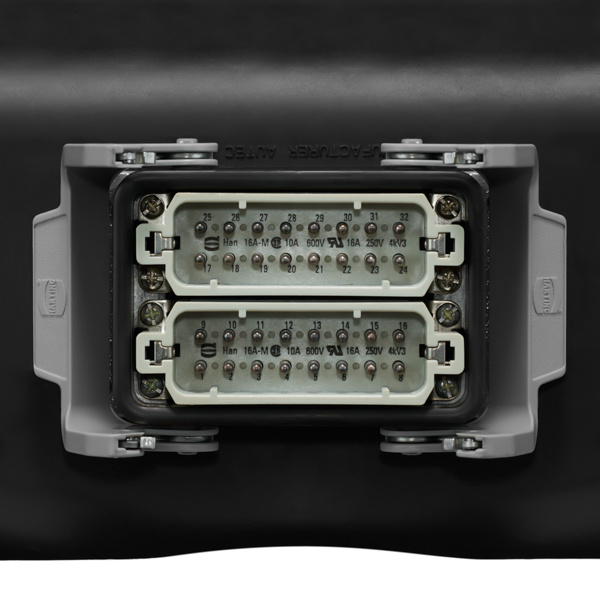
Harting type multipole connector
Harting type multipole connector installed the base station.
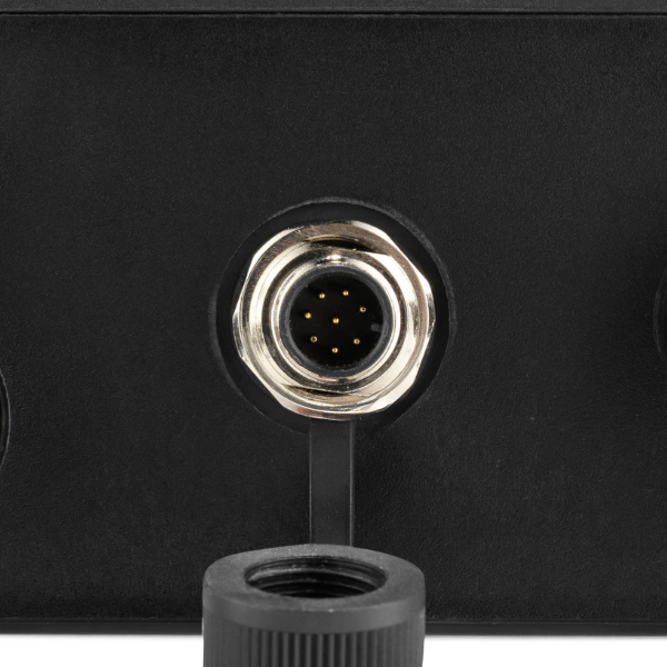
M12 circular connector
Bulkhead M12 circular connector, installed on the base station.
TECHNICAL DATA SHEET
| Power supply |
8-30 VDC
|
|
Max number of outputs
|
4 digital 1 CAN |
|
Rated current of digital outputs
|
2 A (30 VDC) |
| Safety performance of the STOP function (EN ISO 13849-1) | up to PL e, cat.4 |
| Number of digital input | 4 |
|
Dimensions
|
260 x 200 x 190 mm 10.20 x 7.90 x 7.50 in |
| Weight | 2 kg 4.4 lb |
